Previously I had build the AC distribution panel from DIN rail components – but it was set up for a single AC source. This means that it had a set of continuous duty contactors wired in a “transfer switch” arrangement.
This transfer switch arrangement is typical of standard inverter power supply systems in RVs. That means, when plugged into shore power, the inverter is bypassed and connects all devices on the vehicle to external power.
Then, when unplugged, power sourcing is transferred to the inverter/battery stack. In cases where the generator is operating, the AC power usually runs off the generator, again, bypassing the inverter.
That’s a general description of most inexpensive RV power configurations in North America. In our case with the selection of the Victron power assist inverters, it was necessary to reconfigure the power panel to always flow from shore to the inverter, then from inverter to the power panel.
In some ways this is a simpler arrangement, but technically more complex inside the power inverter units.
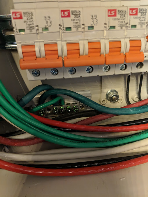
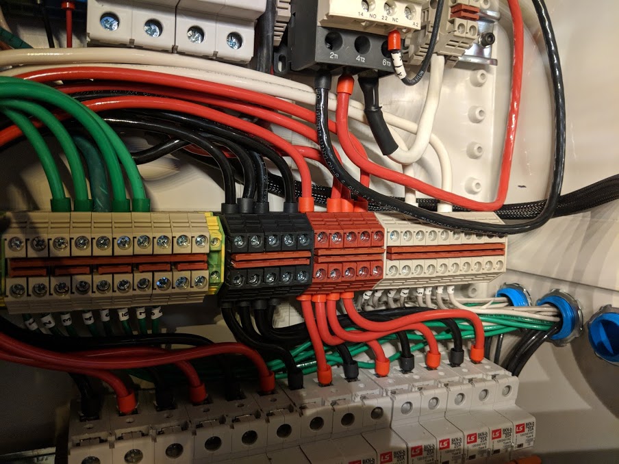
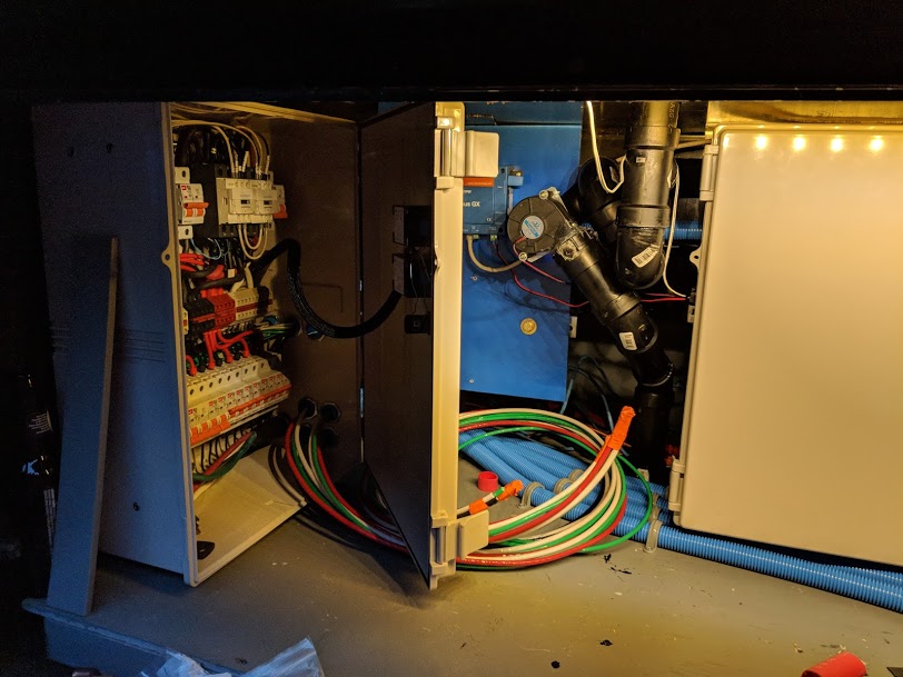
You can see in the photo the additional cable runs to and from the inverters.
I would love to see the full details on how you did your electrical system. I have the skills, resources, and time to implement this, I just need to study your BOM and build-out in more detail.
I don’t really have a bill of materials. It was built in iterations over time while tackling various requirements. Address your requirements first. Material selection is secondary and changes over time based on availability and new technologies.