Wiring the battery pack took some time to get right. I had a rough plan in mind already, driven mostly from the way the pack has to be put together.
I started with the geometry dictated by the bus bars. Those were set because of the layout of the frame itself.
 You can see on the left side of the pack the bus bar that interconnects the lower and upper half of parallel group 8. Given different packaging constraints I’d rather have just had one long cell group.
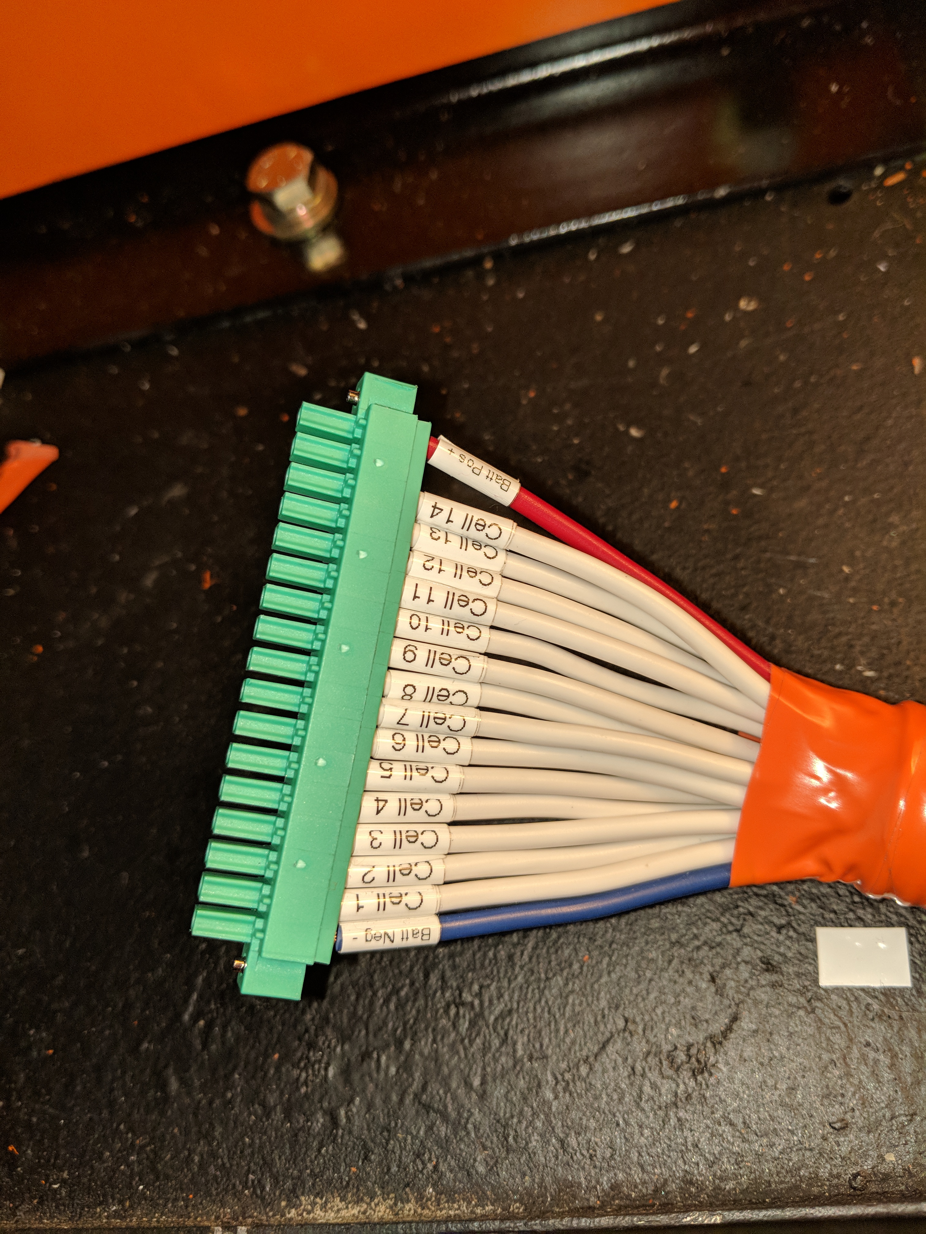
Next was wiring the balance leads. One side of course was connecting to each of the bus bar sections that needed the electrical connection. The other end was the header connector to the BMS. That was pretty much a point wiring and routing exercise.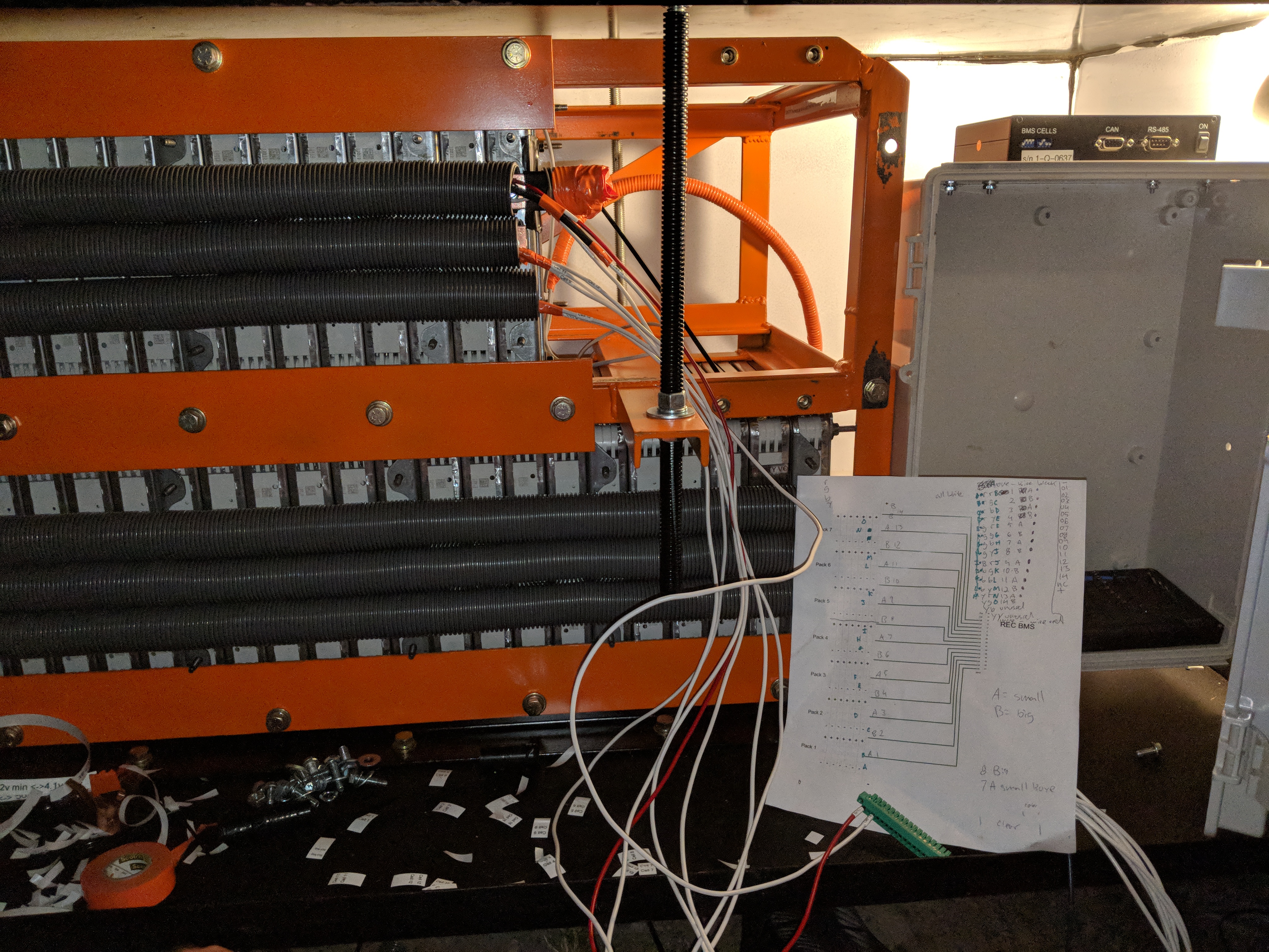

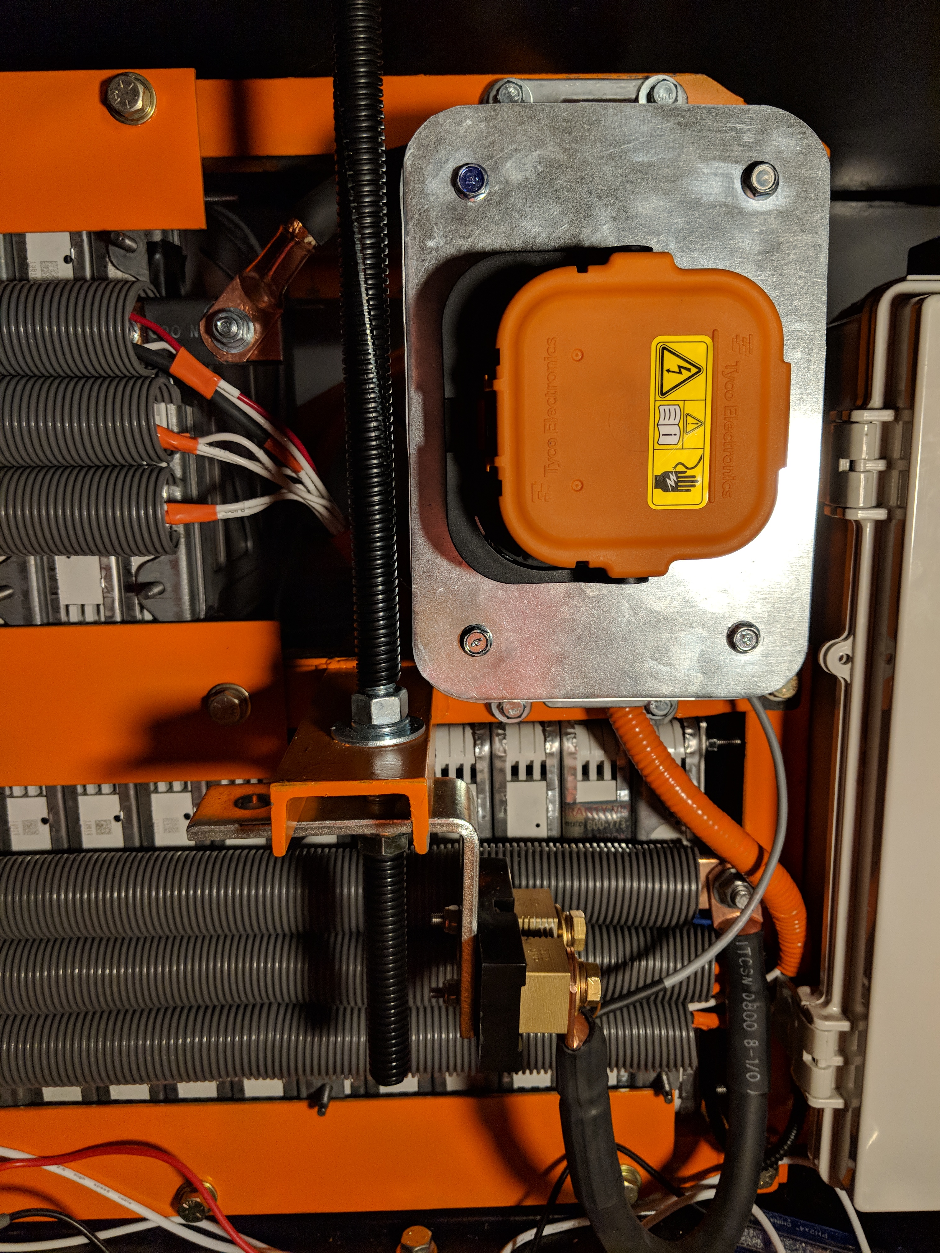
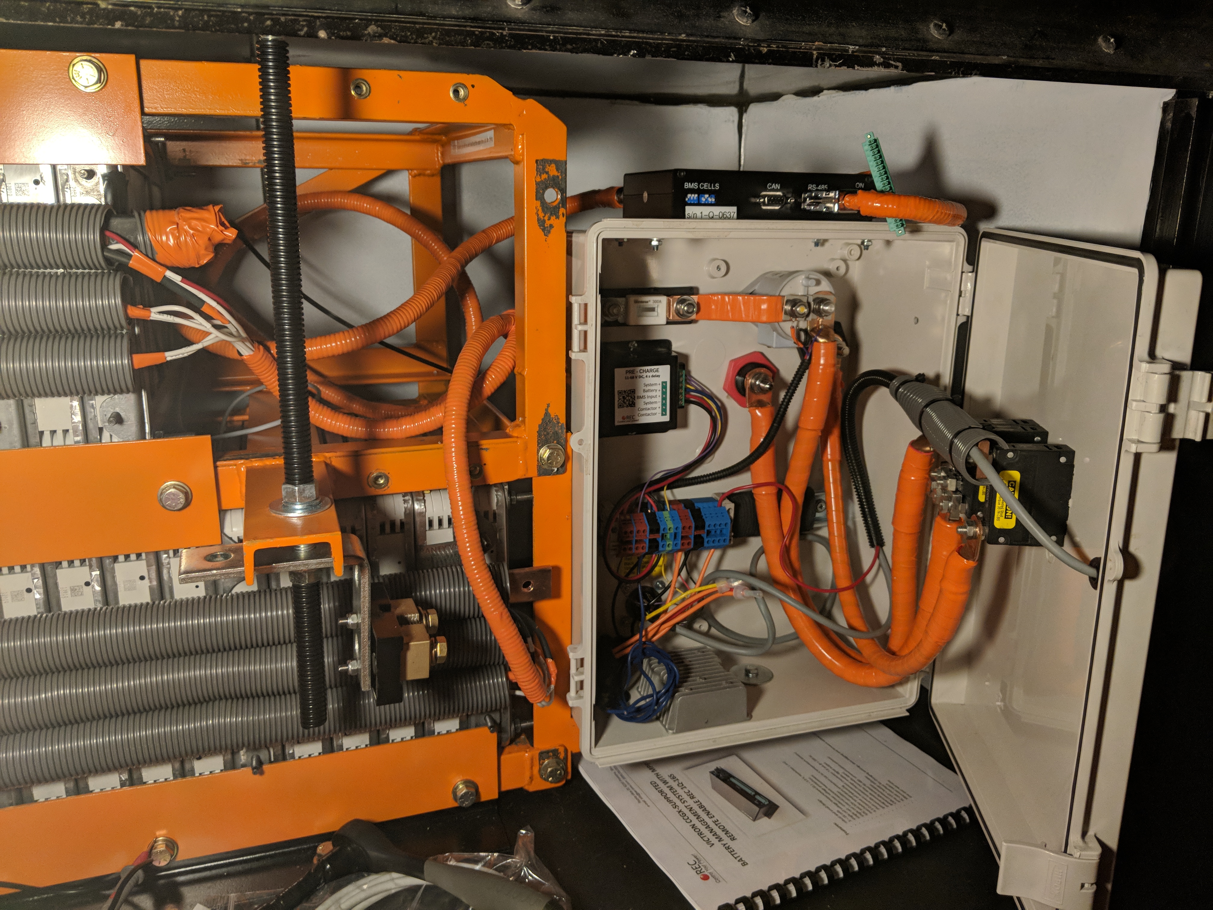
Next was adding the big power distribution cables into the combiner box. This contains the contactor, safety fuse, and other wiring to present power to the rest of the system.
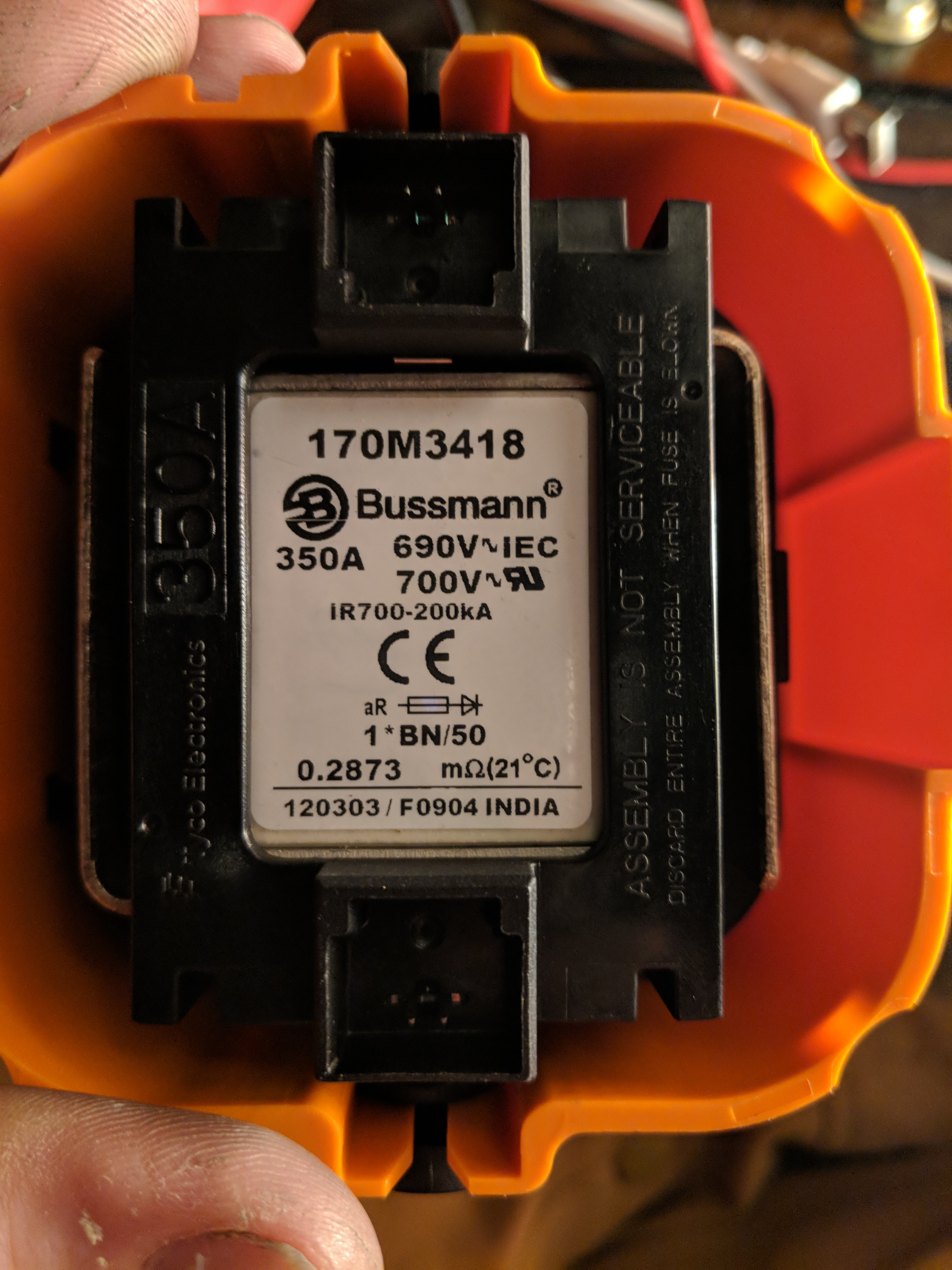
The orange block is a safety disconnect plug. It’s got an integral 350 Amp fuse in it, which is the actual realistic capacity of this system. This goes directly to an internal fuse for 300 Amps.
The contactor is rated for 500 Amps continuous duty, and the shunt is a 300 Amp rated shunt.
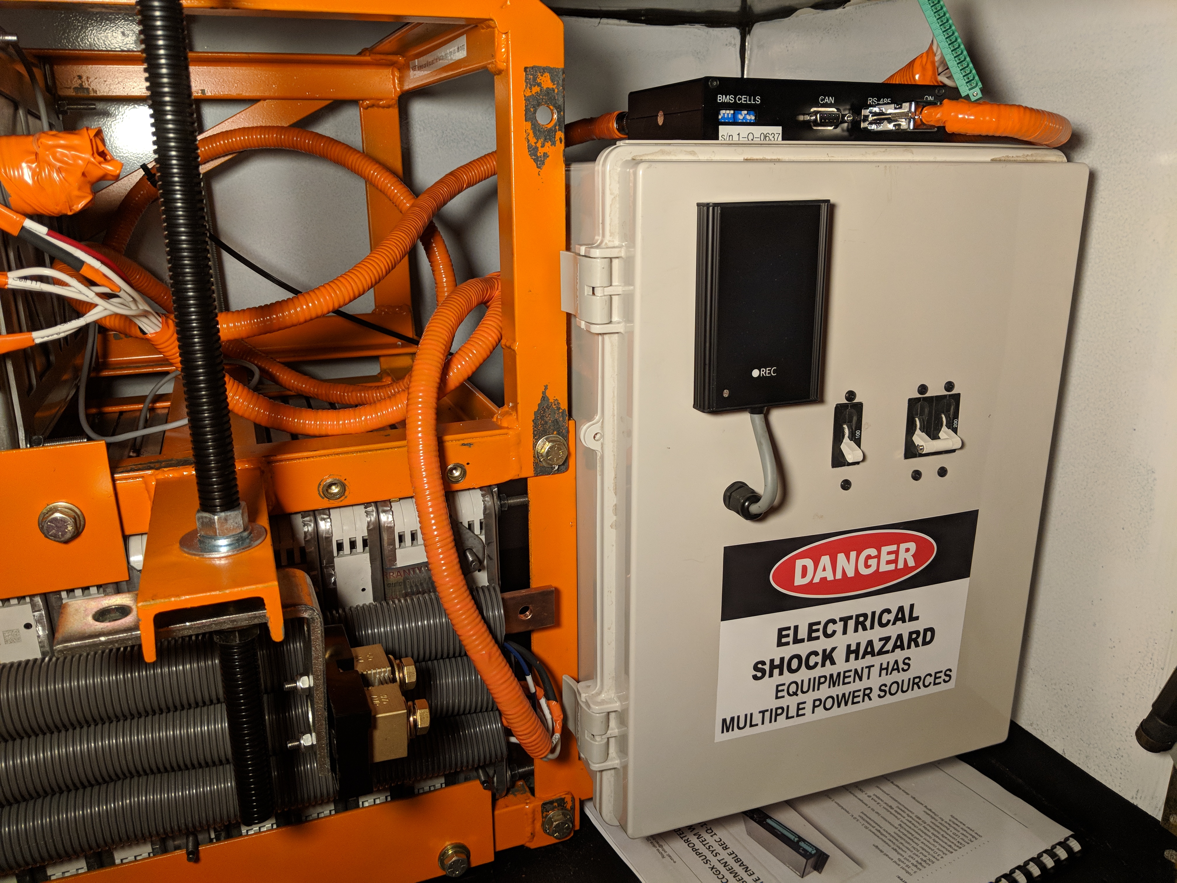
The two DC breakers are 200 and 100 Amps capacity.
The copper bus bars are 1/4″ x 1″, so they have a free-air ampacity of ~400 A DC mode.
The main flexible cables are IEC Welding Cable, so are rated above 400 Amps DC, 100% duty cycle for the lengths in use.
Finally, the BMS itself is programmed for a software defined limit of 100 Amps, of total power differential as detected from the shunt, since that’s the extent of the loads that could be placed upon the system. If it exceeds 100 Amps for any length of time the contactor disconnects as a protection event.
So the battery is capable in normal operating mode of 5600 Watts continuous discharge. (100 Amps x 56 Volts = 5600 Watts)
This is basically a 3:1 operational safety capacity, which was satisfactory for this installation.